
Part 1. Conventional antenna alignment
One of the most important stages of installing a microwave point-to-point link is proper alignment of the antenna system. Any misalignment can cause unstable operation and will decrease the link budget that will affect the overall reliability of the link. While usually straight-forward, alignment on some links can be time-consuming and frustrating if not done correctly. This article will address the alignment challenges sometimes met by engineers and provide general instructions and techniques for achieving optimal link performance. Before you install the microwave radio system, know:
- What is your target Received signal level (also RSSI voltage) from link budget calculation? Typically, the target receive signal level in the field is within +/- 3dB of the theoretical value.
- Azimuth and elevation angles for alignment, e.g. from Pathloss link budget.
Be methodical. Alignment should be seen as two stage process: coarse alignment and fine alignment. Vertical plane alignment (up/down-tilting) is the most challenging.
For coarse alignment, approximate the antenna direction by using Google Earth (or equivalent) to align with a landmark located close to your antenna location in direction to remote side antenna (for instance, a mountain, building, etc.). If you are building a link in an area with few landmarks, a self-made landmark such as kite, balloon, floodlight, flare, or reflection from a mirror might help. A compass or GPS can be another useful tool (noting the difference between True and Magnetic bearings). When using a compass, be aware that large metal structures such as a tower will distort compass readings.
Fine Alignment is normally done using RSSI voltage output port from the radio.
Points to consider:
- Ensure radios are fully set-up and tested on the bench before taking them into the field
- Start by disabling ACM and ATPC and configuring both radios in accordance with link budget (Tx power, modulation, frequency channel). After successful pre-calculated Rx level achievement , ou can enable ACM and ATPC as required
- If possible have a team at each end. It is frustrating and time consuming to travel between the two sites, as the alignment process requires a lot of back and forth
- Only adjust one side of the link at a time
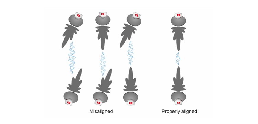
- Be aware of mistaken antenna alignment on a side lobe. Try to push past the best received signal. Radiation patterns incorporate smaller side lobes, in addition to a much larger main lobe. If your received signal is 20dB or lower than your calculated RSL, you may have found a side lobe. Continue sweeping slowly beyond that lobe to see if you can find the main lobe
- Agree on antenna polarization. It can be frustrating to attempt aligning the antenna only to discover that the other team is using the opposite polarization. Do not forget of 17/24 GHz band radios cross-polarization requirement. This should be agreed upon before starting the alignment. If Rx levels remain stubbornly weak, a double check doesn't hurt. Typically radios unintentionally cross-polarized will show a signal loss of 20 - 30dB or greater.
- MW point to point system must have a clear radio line of sight. Even if the remote site has clear eye visibility, radio line of sight is defined by the Fresnel Zone. The Fresnel zone for a radio beam is an elliptical area immediately surrounding the visual path. It varies in width depending on the length of the signal path and the frequency of the signal. If a hard object, such as a mountain ridge or building, is too close to the signal path, it can reduce strength of the radio signal and desired Rx level will not be achieved. This happens even though the obstacle does not obscure the direct, visual line of sight. The necessary clearance for the Fresnel zone can be calculated, and it must be taken into account when designing the link
- During short link alignment over urban areas try to avoid alignment to reflected signal from a reflective plane such as a rooftop or lake in the middle of the path. In order to avoid such mistake, always start Vertical plane sweep from top, meaning antenna should be aligned “into the sky” before you begin.
Read the second part of this article, to learn how to make antenna alignment super-effective, fast and totally reliable